Expert Blog
Motion matters: designing a motion control system

Compact motion control systems are essential to applications ranging from surgical robots through to drone flight. While their design is based on the laws of motion, perfecting it is an iterative process, and dedicated motion engineering expertise is key to fast and effective development.
maxon engineer Ronak Samani discusses the process to design a motion control system.
The basic task of any motion control system is to manage the movement of a load. However, for many applications, the crucial element is to achieve this with precision and reliability. Motion control is required across a diverse range of sectors, from manufacturing to health care. But with compact systems, typically generating below 1 kW power, the need for precision is the highest. The smaller the scale, the higher the level of accuracy, stability, and fine motion control that’s required – think manoeuvring a robotic arm during a complex procedure compared to controlling a crane at a shipping port.
Within this realm, we’re talking about applications such as surgical tools that need to operate at micrometre precision within the human body, or extremely light weight devices, such as those involved in aerospace or space exploration. Within these compact motion systems, the ideal motor designs include the DC motor and the brushless DC (BLDC) motor, preferred because of their small size and relatively high torque generation.
Open-loop control
While the motor, or motors, do the actual work, controlling their motion is vital. The most basic control principle is open-loop control, where the motor moves at a certain acceleration, speed, deceleration, and position, based only on the commands it’s given, and without checking if it achieved the desired result.
This method is used by applications that are inherently stable, meaning the system’s response is usually known as interference is limited or varying conditions will not affect the system’s operation. This could involve applications such as a fan for cooling electronic devices, where the airflow requirement is approximate and a precise level is not critical. Or a conveyor with a generally constant load, where the torque requirement doesn’t vary significantly and maintaining approximate speed is sufficient.
In an open-loop system, the motor operates on the applied voltage, with no feedback to verify how fast or how far it has moved, relying instead on predictable loads and mechanical devices to stop the motion. To achieve this, a compact DC motor can operate directly from the voltage supply, sized accordingly and with current limits. For open-loop applications using a BLDC motor, which might be selected to achieve higher speed or torque, or longer service life, this design always needs a controller to enable electronic commutation, the switching of the phases to make the motor spin.
Closed-loop control
To optimise precision and accuracy, closed-loop control techniques are required. Closing the loop means monitoring the output variable using sensors to provide feedback data. This information is used by the control device to continually modulate motion according to parameters such as torque, speed, and acceleration.
A motor controller is required to manage these parameters, acting on information provided by a sensor such as an encoder, which detects movement of the motor shaft or another moving part of the motion system. The encoder uses sensors that generate electrical signals, which the controller interprets to determine angle, direction, and speed.
Ultimately, the control of an application is always rooted in torque control, which is necessary to set mass into motion and manage acceleration and deceleration, including tasks like lifting, lowering, or holding objects in tension. Consequently, current control loops are the key feedback processes within these devices. As current and torque share a linear relationship in DC brush and brushless motors, a current controller sets the input torque command, which it converts to a current command, measuring the current applied and correcting as required.
The motion controller
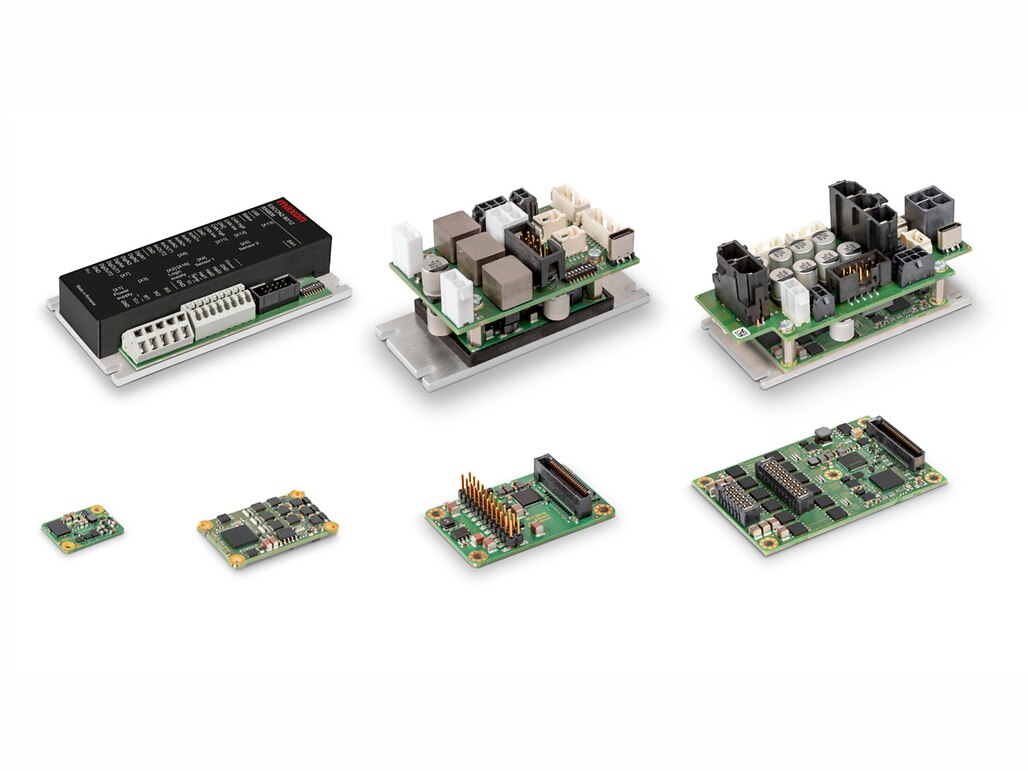
In the hierarchy of motion control, the motor controller is next in line to the motor. This device includes a power stage that modulates the voltage and current supplied to the motor to execute the motion commands. Motor controllers, like maxon’s Escon speed controller or Epos4 position controller, are configurable, meaning that its built-in firmware lets you adjust settings like speed, torque, and position limits, as well as communication options.
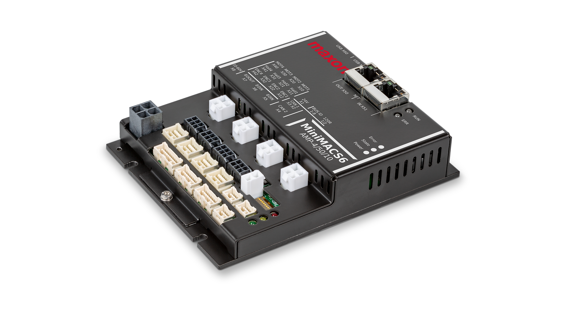
The motion commands themselves are generated by a motion controller, which is the next level up in the architecture. A motion controller, like maxon’s MicroMACS6 or MiniMACS6, is programmable, meaning you can set the motion trajectory plans and interpolation, including parameters such as torque and acceleration. Within this hierarchy, the motion controller commands the motor controller, or coordinates several motor controllers within multi-axis applications, to execute the motion commands.
The choice of operating mode with closed-loop operation dictates the architectural responsibility between motion and motor controllers. In a profile-based, point-to-point operating mode, the motion controller sets parameters and commands the motor controller. The motor controller is then responsible for processing motion profiling or trajectory generation, often based on a trapezoidal profile, where it accelerates at a constant rate to a constant speed, maintains that speed, and then decelerates at a constant rate to stop, forming a trapezoid shape when plotting speed versus time.
This kind of point-to-point mode is not suitable for real-time applications as communication between the motion controller and motor controller exchange pre-defined setpoints at a fixed rate and cannot react to external events or real-time control inputs.
Real-time control
When real-time control is required, a cyclic operation mode can be used, with responsibility for trajectory generation shifting to the motion controller that processes motion profiling and transmits updated set values to the control loops to deal with ongoing inputs. This also requires real-time communications using protocols such as CANopen or EtherCAT.
Moving up to a further level, in a strongly coupled application, maximum responsibility is given to the motion controller, which processes motion profiling and control loops across multiple axes. Here, the motor controller is configured purely as a current controller and serves only as a power amplifier, operating to the commands of the motion controller.
The difference is that while the cyclic operation mode might still operate to a pre-set, point-to-point profile, albeit reacting to external inputs in real time, in a strongly coupled application, the motion controller can calculate advanced trajectories in real time – and across multiple axes.
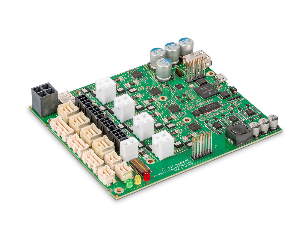
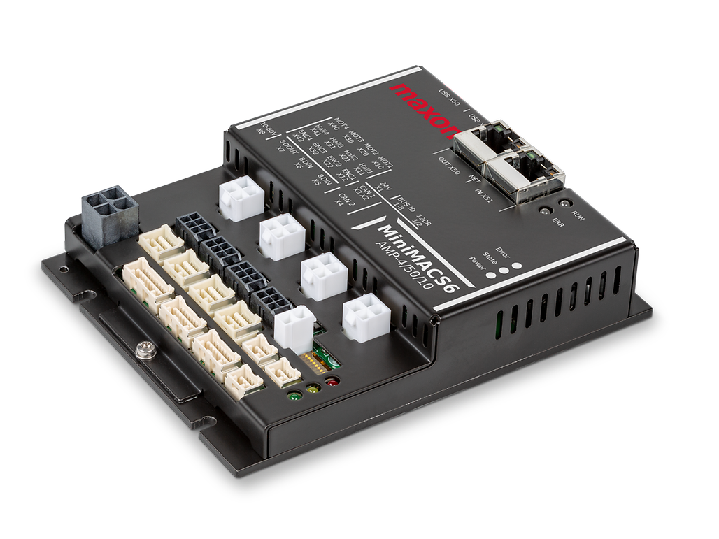

MiniMACS6-AMP-4-50-10
Controller selection process
Selecting a controller requires a holistic approach, which goes right through to the requirements placed on the motors themselves. It’s crucial to perform a thorough situational overview of the application, defining the mechanical layout and intended motion control task, along with boundary conditions such as spatial envelopes, compliance factors, environmental conditions, and service life requirements.
While system design and controller selection are based on the principles of motion, tailoring the solution is an iterative approach rather than a theoretical study. Clearly describing the drive system in its environment, and clearly defining the requirements from outset, helps designers arrive at an optimum solution more quickly. In fact, the most common challenge we see during system design and selection is insufficient formulation of drive system requirements.
Selection tools, such as drive system configurators, are extremely useful to assist in motion system development. But to ensure all bases are covered, reviewing a comprehensive plan with an engineer dedicated to drive system design will ensure that any design issues are identified and resolved early in the process, without compromising the design in later stages.
Most importantly, if the drive system plays a central role in the overall application, dedicated engineering expertise will make sure that the motion cycle is optimised to achieve the best performance.